Target Boards
The MSP430 can be programmed while inside its final circuit, if the proper electrical connections are available, or outside of its intended place by using a target board. These boards are built in a way that the chip can be inserted temporarily, programmed, and then removed and mounted into the circuit in which it's intended to be used. A well built target board will also make it possible to prototype, or connect to other circuits so that the chip can be used while still in its target board. TI makes nice target boards for some of the form factors used for their MSP430's, such as the MSP-TS430PW28. While a little costly, most of the expense comes in the fancy, spring-loaded, zero insertion force (ZIF) socket for holding the chips. For a little more, you can even get bundles that include a full programmer. Target boards are not too difficult to design, either; we'll look at how to do just that in a later tutorial.
A fancier type of board is the experimenter's board (also may be called a development board). This board can be similar to a target board and use a socket to make the chip placement temporary, or it can have the MSP430 soldered in place. Experimenter's boards come with other parts like LED's, buttons, and perhaps speakers, serial or ethernet ports, and a wide variety of devices or connections that interface with the outside world. TI makes a few of these, such as the MSP-EXP430F5438. Other vendors like Olimex also make this type of board, usually at a lower price tag, but sometimes with older families of the MSP430.
Programmers
The MSP430 programmer is officially referred to as a Flash Emulation Tool (FET). These tools serve a dual purpose; they write programs to the MSP430, and they also can control the chip manually to allow for debugging of the program (see the discussion on debugging in the compiler section).
TI has two types of programming connections. You can use a 4-wire JTAG connection, which needs four pins of the MSP430 to write the program to the chip's memory, or you can use a 2-wire (Spy-bi-wire, or SBW) connection, which obviously needs only two pins to write the program. The 4-wire JTAG can be used to program any of the MSP430's, but the SBW only works with some of them. While you might think the SBW interface only works on some of the smaller, lower end chips, it's not the case; in fact it seems TI is including SBW capability in all of its new designs, including some of the new and powerful MSP430x5xx family. (A list of compatible parts can be found in slau157n. Look for Table 2-1.) The real trade-off for using SBW is the programming speed; SBW runs about ten times slower than JTAG. However, MSP430 programs tend to be quite small, often less than 2 kb in size. Unless you're really impatient, programming and debugging speed shouldn't be much of an issue, unless you're working in time critical environments.
The standard TI FET comes in a USB interface, though an older serial-port interface is also available. This FET can program by either JTAG or SBW through a 14 pin (2x7) header pin connector. Other companies have made their own equivalents to the TI programmer, often at a lower price.
If you are satisfied with SBW programming, there are some cheaper options available. The TI eZ430 system has an FET interface in a USB stick form factor (picture here). Unfortunately, the pins are very close to the computer, so your board must also be close, or you'll need to make your own cable to connect your board to the stick. (Remember that SBW is a 2-wire interface; you might notice the connection to the USB portion has 4 pins. The MSP430 also needs power, and most FET's can provide power directly. Two more pins are needed for Vcc and ground. The minimum needed for JTAG would be 6 pins.)
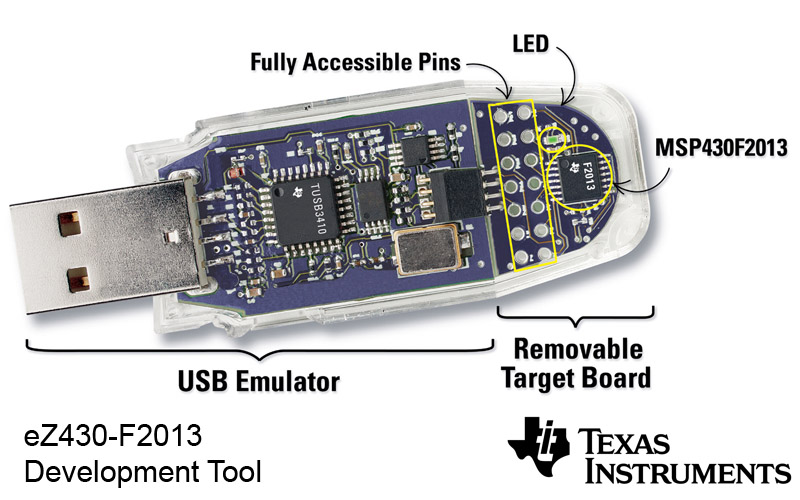
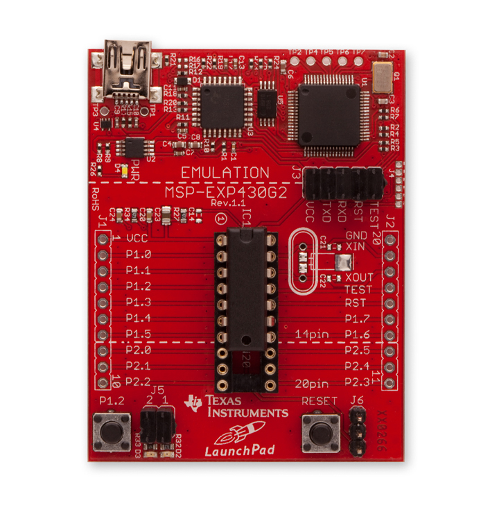
The LaunchPad comes with its own SBW FET built in. The emulation portion of the board can also be used to program MSP430's externally. A set of 6 pins are available for this, giving power, the SBW interface, and two extra pins for communicating through the USB controller on the board.
Compilers
Two professional compilers for the MSP430 also make free versions available; IAR Systems and Code Composer Studio. The free versions limit the code size you can create (4 kb for IAR, 16 kb for CCS), but many of the MSP430 variations have less memory than this anyway. For larger programs, you can either purchase the full compilers, or use the mspgcc open source compiler. Information on using mspgcc will be given at some point on this blog, but for the purposes of the tutorial we'll use TI's Code Composer Studio. Those who prefer IAR's compiler should be able to do so without much difficulty from the tutorial here.
One of the most important tools for a development environment is a debugging interface. IAR and CCS both come with one built in to the IDE, but mspgcc users will need mspdbg to do debugging. The debugging feature allows you to step through the code and see how it changes the settings and configurations of the MSP430 step by step, helping you to verify that the system is working the way it should and to view the contents of the registers and variables in memory. Early on in the tutorial posts we'll look at using the debugger effectively.
Power
The LaunchPad is powered through the USB interface, and whenever an FET is used this option is available. If you want to implement your design in a stand-alone system, however, you'll need to provide power to the circuit in some way.
The MSP430 is an ultra-low power device, and performs very well using standard consumer batteries. The MSP430 will run with anywhere between 1.8 V and 3.6 V, though at least 2.2 V is needed to do any programming to the chip. Keep in mind that the speed at which the chip is able to run also depends on the voltage; though it's capable of running up to 16 MHz, at 1.8 V an MSP430F2001 cannot run any faster than 6 MHz. This image is an excerpt from the MSP430F2001 datasheet, showing how the supply voltage affects the operating frequency.

Check the datasheet for your particular MSP430 device for a similar plot to see what frequencies are available at the voltage you choose to power your design.
Aside from consumer batteries, you can also power your design from the wall if you use a transformer and voltage regulator. Later on we'll look at the ideas to consider in using a voltage regulator. You may be interested in looking into using a solar cell to power your design, or other creative ways to get power.
Following the Tutorial
This tutorial will use the TI LaunchPad with its SBW emulator to explain how many of the features of the MSP430 work and how to use them effectively. Examples will be done using CCS v4 as the development environment. If you have these two pieces (for a total price of $4.30!), you'll have enough to get started. If you happen to have another emulation tool or target/experimenter's board, feel free to use what you already have; everything done in the tutorial is easy to modify to whatever MSP430 platform you're using. When we move on to interfacing outside of the LaunchPad system, we'll provide some good ideas on how to do that cheaply and cleanly. Once you have the basics down, you should be able to design any system in which you can put in and program an MSP430.
13 comments:
Dude, you rock!
Nicely explained ... COmmendable effort i got some concepts out of it
fantastic explanation so far, much cleaner than any of the other introductions to MSP430 programming I've read up to this point.
amazing dude, thank you very much for your great explanations :)
Thank you for taking the time to write all these posts and share your work! It is very helpful and I'm really looking forward to when you get into the further things down the road! I hope you keep it up!
Your site is very good.
Is 2.2V required for JTAG for all chips?
The MSP430F5438A for example mentions 1.8V min voltage for flash write.
Hi, the link to power creative ways is private. Are you aware of that? Is there another way to look at that video?
Thank you.
No, thanks for letting me know. One of the problems with linking to online resources is that links break if the owner changes anything. I've updated the link to the current video, but if it ever breaks just search youtube for "msp430 grapes", and you'll find it. =)
One tutorial a day keeps the Forum away :-)
great series of tutorials!!
Happy to find this blog!
So far so good :)
Thanks
You really know what you're doing. Thanks
Great Start!!! lemme explore more.. I am starting Programming today :)
Post a Comment