21 August 2010
Still Alive
I've had a number of people ask about the long delay since my last post, so I thought I'd put a quick note up to give you an update. My deadline to deliver the instrument I'm building for my Ph.D. research is coming up in a couple of weeks. As such, I'm spending 10-14 hours a day in the lab, and haven't had a moment to think about the blog in a while. Once the instrument is delivered, however, there will be lots of time opening up. I have had lots of ideas and do have lots of plans for this site, so thanks for your interest and patience! I'm really encouraged by the good reviews I've gotten for what I've written up so far. I do really think the MSP430 can be a very important tool in developing instruments for use in or out of a laboratory, and we'll get to try some out soon.
03 August 2010
Tutorial 10-b: Interrupt Examples
GPIO Interrupt Example
The first example we'll do uses the Port 1 interrupts; this code is easily changed for any port number used in your particular device. This code will show how to do the DCO example we did in Tutorial 08-b, which demonstrates changing the DCO, using interrupts.
First, we need to configure the port to use interrupts. The LaunchPad button is on P1.3, so all of our concern will be on that pin. The pin needs to be configured as an input. Since the default state of the pin is logic 1, a high-low transition (a drop from 1 to 0) should be used to signal the interrupt. We can code this using:
P1IES |= BIT3; // high -> low is selected with IES.x = 1.
P1IFG &= ~BIT3; // To prevent an immediate interrupt, clear the flag for
// P1.3 before enabling the interrupt.
P1IE |= BIT3; // Enable interrupts for P1.3
We've enabled the interrupt for P1 now, and a high-low transition caused by the button press will set the interrupt flag in P1IFG. The processor, however, isn't set to recognize maskable interrupts like P1IFG. We can turn on the interrupts with:
_BIS_SR(GIE);
or equivalently:
_enable_interrupt(); // Note the singular name here! It's not interrupts.
The first method parallels the bis.w instruction in assembly used for this command, and can be used to configure the SR in one step with other options, such as low power modes. The second method is a little more human readable, and works well enough if you don't need to enable any LPM's.
Next we need to write the ISR. Something like this will work:
#pragma vector = PORT1_VECTOR
__interrupt void P1_ISR(void) {
switch(P1IFG&BIT3) {
case BIT3:
P1IFG &= ~BIT3; // clear the interrupt flag
BCSCTL1 = bcs_vals[i];
DCOCTL = dco_vals[i];
if (++i == 3)
i = 0;
return;
default:
P1IFG = 0; // probably unnecessary, but if another flag occurs
// in P1, this will clear it. No error handling is
// provided this way, though.
return;
}
} // P1_ISR
The port interrupts can be sourced from 8 port pins, and so the ISR needs to decide what to do with each possible interrupt. The switch statement in C is ideal for this task, and is used here to single out a BIT3 flag. If, for some reason, the MSP430 is flagged with a different Port 1 interrupt, it simply clears the flag and moves on. Since none of the other flags are enabled, this should never happen, but it's good coding practice to include something like this. Error handling would be ideal, but it's not done here.
Note that since the P1 interrupt has 8 sources and individual flags, you need to clear the flag manually. Don't forget to do this, or your code will continually keep interrupting! This code makes use of three pre-stored values for BCSCTL1 and DCOCTL and increments through them each time the interrupt is called. These values, as well as the counter i, need to be global for the ISR to see them, and so they are declared outside of the main() function. See the whole code put together in interrupted-1_G2211.c.
Timer_A Example
As a second example, we'll do something similar to a project I'm working on and turn a light on and off using a relay switch. I've coded this using a switch on P1.6 so that you can observe its behavior on a LaunchPad using the green LED instead of the actual relay. If you have a relay, be sure to connect it correctly to prevent too much current draw from your MSP430. Using the 1 MHz calibrated DCO divided by 8, Timer_A will count up to 62,500 in 0.5 s. In my actual application, I'd like to turn the light on for a few hours, then turn it off for a few hours. That's easier to do with a slower clock, and an ideal application for the LFXT1 clock source. But, since we haven't covered that yet and many people likely do not have the crystal soldered to their LaunchPad's, we'll do more frequent on/off cycles to simulate the actual process. We'll use the DCO to turn the light on and off in 1 minute intervals. To do this, we'll make use of the Timer_A up mode and interrupt using the CCR0 registers. (Yes, this is essentially a fancy version of blinky. Turns out "Hello, world!" is actually useful in microcontrollers!)
We configure the timer with the following:
TACCR0 = 62500 - 1; // a period of 62,500 cycles is 0 to 62,499.
TACCTL0 = CCIE; // Enable interrupts for CCR0.
TACTL = TASSEL_2 + ID_3 + MC_1 + TACLR;
The long string of assignments to TACTL are, in order, select SMCLK as the clock for Timer_A (runs off the DCO by default), select input divider of 8 (1 MHz SMCLK becomes 125 kHz), select up mode, and clear the count in TAR. These values are defined in the device header file so that you don't have to constantly manipulate bits by hand. The mnemonics are easier to use most of the time. (For other configuration options, see the Timer_A section in your device's header file.)
The ISR may look something like this:
#pragma vector = TIMERA0_VECTOR
__interrupt void CCR0_ISR(void) {
// no flag clearing necessary; CCR0 has only one source, so it's automatic.
if (++i == 120) {
P1OUT ^= RLY1;
i = 0;
}
} // CCR0_ISR
Again, we're using a global variable i as a counter, and presumably have defined RLY1 to be BIT6 in the program header. Every time a flag occurs (twice a second) the counter is incremented. If we've reached 120 (60 s at 2 Hz) the relay control is toggled and the counter resets.
The complete code for this example is in interrupted-2_G2211.c. For you impatient folks, feel free to adjust the timer period to whatever value preserves your sanity.
These two examples should get you started with interrupts. As always, feel free to ask questions or suggest other helpful tips!
Tutorial 10-a: Something Completely Different (Interrupts)
I realized half way through the last tutorial that we need to take an aside for now. One of the unfortunate aspects in microcontrollers, especially for those with no prior experience, is that you run into chicken-egg dilemmas all the time. How can you teach timers without interrupts? How can you teach interrupts without something to cause interrupts, like timers? It takes some patience, but with some experience (and lots of examples!) things start to settle into place. In the mean time, I apologize for the occasional jump in topic. For that matter, we're not entirely done with previous topics either, and will revisit some of the more advanced concepts of GPIO, Clocks, and so forth in the future.
So what exactly is an interrupt? Hopefully you're familiar enough with C programming (if not, I highly recommend spending some time with a good book; I suggest the C Primer Plus (5th Edition) ) to have a good handle on function calls. Microcontrollers use function calls as we've seen before, just as your personal computer does. But microcontrollers also interface with the outside world, and sometimes you need to perform a specific task based on what happens outside the circuit. One option would be to continuously poll an input (or sequentially poll a set of inputs) to see if anything needs to happen and call the appropriate function accordingly. Unfortunately, this ties up the processor so that it can't do anything useful in the mean time. Perhaps worse, the processor keeps chugging along, using up power doing nothing but waiting to see if it's got a job to do. The better option is to have the outside signal interrupt the processor (from its current task or its nap) to get a task done and then allow the processor to go back to what it was doing. This ability is implemented in the aptly named interrupt service routine (ISR).
The Interrupt Handling Procedure
In order to control multiple sources at once, the MSP430 needs to have some definite organization; who gets priority over the other peripherals? How do we keep track of where we were before? To do this, the MSP430 is designed with a clean and efficient procedure to handle interrupts.
So what exactly is an interrupt? Hopefully you're familiar enough with C programming (if not, I highly recommend spending some time with a good book; I suggest the C Primer Plus (5th Edition)
The Interrupt Handling Procedure
In order to control multiple sources at once, the MSP430 needs to have some definite organization; who gets priority over the other peripherals? How do we keep track of where we were before? To do this, the MSP430 is designed with a clean and efficient procedure to handle interrupts.
- If a peripheral's interrupt is enabled, the appropriate signal sets the interrupt flag in one of the peripheral's registers.
- If the processor is allowing interrupts, the presence of a peripheral interrupt flag sets a general flag to the processor.
- The processor finishes any instruction it's currently doing.
- The processor saves it place by copying the address where it's currently executing instructions (the value in the Program Counter (PC) register) to the memory stack (this is called "pushing onto the stack").
- The processor saves its current status by pushing the Status Register (SR) onto the stack.
- The interrupt that currently has the highest priority is selected if there are multiple flags set. Check your device's datasheet for a list that shows the priority of the possible interrupts.
- The interrupt flag is cleared, unless the peripheral has more than one type of interrupt. In that case, you have to clear the flags manually.
- The SR is cleared, which disables any further interrupts during the ISR handling and wakes up the processor from any low power mode (LPM). Note that only "maskable" interrupts are disabled by the SR clear; this means "non-maskable" interrupts, such as a reset, are still possible during an ISR.
- The address of the interrupt vector is copied to the PC, directing the processor to start executing code from that address on.
From the start of an interrupt signal to the start of ISR execution can take anywhere from 6-12 clock cycles of the processor, depending on exactly what's going on when the interrupt is flagged. (This latency isn't much, but must be handled differently for time-critical event handling.) If the chip is operating at 1 MHz, that's anywhere from 6-12 μs for the processor to respond to an event.
When the ISR finishes, the processor executes the return from interrupt sequence, which consists of just two steps:
- Move the original SR value from the stack to the SR (this is called "popping" from the stack).
- Pop the original PC value from the stack to the PC.
This sequence takes another 5 cycles to complete, after which the processor returns to what it was doing. Note that if the MSP430 was in an LPM before the interrupt, it returns to the same LPM after the ISR handling with no further instruction from the code necessary. You only need to give a different instruction if you don't want the MSP430 to reenter the LPM. We'll see how to do that soon, when we discuss the low power modes.
Coding Interrupts
Writing an ISR is very similar to writing encapsulated functions in C, but requires some special syntax that you may not have seen before. Every ISR has this structure:
#pragma vector = <VECTOR_NAME>
__interrupt void <ISR_NAME> (void) {
ISR code here
}
The keyword #pragma is used in C to signify a special operation peculiar to a compiler. (If you were to compile your MSP430 code with another compiler, such as gcc, it would simply ignore this line, leading to potentially unexpected errors.) In this case, it tells the MSP430 compilers that the following code is to be referenced for the particular interrupt named. VECTOR_NAME is essential, and must follow the conventions for the particular peripheral interrupt being written used in your device's header file; the address of the start of the ISR in the code memory is recorded in the address defined by the header as VECTOR_NAME. Take careful note that the #pragma line does not have a semi-colon at the end.
__interrupt signifies the start of the ISR. You can name the ISR anything you'd like, but conventionally coders use something descriptive, such as P1_ISR for a Port1 interrupt, or TA0_ISR for a Timer_A interrupt.
Beyond that, everything remains the same as we're used to seeing. There's no special code needed in C to start the return sequence, but in assembler you need to manage this using the reti instrunction.
Unused Interrupts
What happens if an interrupt is called and you don't have an ISR written for it? The results are unpredictable, depending on what value is inside the interrupt vector. The safest method to protect from this is to write an ISR for every interrupt, doing nothing, or perhaps entering an infinite loop, for interrupts not used. (The infinite loop method makes debugging clearer; it's obvious where you get stuck that way!) This convention doesn't take much code space in the MSP430, but can make your simpler projects a little more complicated to the outside viewer. Another way to handle this problem is to be certain that unused interrupts are disabled so that they can't ever flag the processor. Not controlling interrupts can cause serious problems, however, so be sure to try to use good coding practices whatever you do.
This part of the tutorial on interrupts is long enough, so the following post will give a couple of examples to get you started using what we've learned here.
01 August 2010
Tutorial 09: Timers
Now that we can configure the clocks in the MSP430, we can use them to drive peripherals. Peripherals are hardware that may be built into the chip itself or added on by us. Controlling peripherals is where the microcontroller really comes to its own, and is likely the reason you're learning about the MSP430. The first peripheral we'll examine is the Timer_A system.


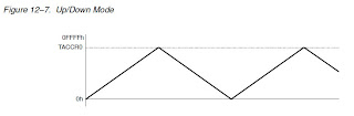 There are three modes to operate Timer_A. Which one we use depends entirely on the application. The first mode is what we call the continuous mode: Timer_A acts just like a 16-digit, binary odometer; it counts from 0 to 0xFFFF and then "rolls over" to 0 again. The second mode is called up mode; here, just like in continuous mode, it counts up and rolls over to 0. This mode, however, lets you choose how high up the timer counts before rolling over. The third mode, up/down mode, is similar to up mode in that you can program the upper limit. It differs in that rather than rolling over to 0, it turns around and counts down to 0. When you would choose to use the different modes may or may not be immediately obvious, so as you peruse articles on this and other sites, take note of how each mode is used when you see them in examples.
Registers
First, note that there is also a Timer_B system available in some devices, which in most respects is just like Timer_A. None of the value line devices have this system, so if you're eager to use this peripheral in another device, learn about Timer_A and then refer to the Family User's Guide for more information.
A timer is really nothing more than a counting mechanism that is tied to some type of regular interval provided by a clock. The Timer_A peripheral is what we call a 16-bit timer. This definition simply means that the timer counts from 0 in binary to 0b1111111111111111, or 0xFFFF in hex, 65,535 in decimal. Simple enough, and very useful when we know how to manipulate the behavior of the timer.
Timer Modes
Timer Modes


In addition to the three ways of counting in Timer_A, there are also a few ways we can make use of the counter. Timer_A has the ability to set "checkpoints" in its counting (Value Line devices only have two, but other devices have a third). TI calls these checkpoints Capture/Compare Registers. The most basic use of these registers is to set values at which the counter flags the processor to do something special. In fact, one of these registers is what is used to set the upper limit in up and up/down mode. The other register only flags the processor and allows the timer to keep on counting. (This is also the behavior of the first register in continuous mode.)
This type of use is the Compare mode of the register; we set a value that is compared to the current count in Timer_A. If the values are equal, it signals that's the case to the processor. Capture mode behaves a little differently; the timer waits for some type of signal (often from some sort of input) and then records the current value of the timer in the register without stopping the timer, somewhat like the lap time function of a stopwatch.
Registers
With so many ways to use Timer_A, you can probably imagine it corresponds to a lot of registers in the MSP430 to use and control the timer. There are, in fact, at least seven registers used in any device with the Timer_A peripheral. Let's take a look at each of these in more detail. In your Family User's Guide, turn to pages 12-20 through 12-23 to see the register maps.
- TACTL -- The Timer_A Control Register is used to set up the link between the timer and a clock and select the mode used.
- The TASSELx bits (8 and 9) tell the timer which clock to use as its source.
- The clock frequency can be divided by a further factor of 2, 4, or 8 using the IDx bits (6 and 7). (Note that this is further division to any divisions done from the clock source for the clock itself; you could potentially have a total division of up to 64 from your clock source for this peripheral.)
- The MCx bits (4 and 5) select the particular mode for the timer to use. Note particularly that setting these bits to 0 (the default setting on POR) halts the timer completely.
- TACLR is bit 2. If you write a 1 to this bit, it resets the timer. The MSP430 will automatically reset this bit to zero after resetting the timer.
- TAIE and TAIFG (bits 0 and 1) control the ability of the timer to trigger interrupts; more on this soon!
- TAR -- The Timer_A Register is the actual counter; reading this register reports the current value of the counter.
- TACCRx -- The Timer_A Capture/Compare Registers, of which there are two in the value line devices (TACCR0 and TACCR1) are where particular values we want to use are stored. In compare mode, we write values here where we want the timer to signal an event. Particularly, TACCR0 is used to store the value to which we want Timer_A to count in up and up/down mode. In capture mode, the processor will record the value of TAR when the MSP430 is signaled to do so.
- TACCTLx -- The Timer_A Capture/Compare Control Registers correspond to the TACCRx registers. These set the behavior of how the CCR's are used.
- CMx (bits 14 and 15) change what type(s) of signals tell the timer to perform a capture.
- CCISx (bits 12 and 13) select where the input signals are taken.
- SCS and SCCI (bits 11 and 10 respectively) change the synchronicity; the timer normally operates asynchronously to the input signals. (Yeah, I don't entirely understand this yet either. Watch for a future post to explain this further.)
- CAP (bit 8) changes whether capture mode (1) or compare mode (0) is used.
- OUTMODx (bits 5-7) select various output modes for the CCR's signal when the timer flags a capture or compare event.
- CCIE and CCIFG (bits 4 and 0) are more interrupts associated with the CCR's.
- CCI and OUT (bits 3 and 2) are the input and output for the CCR.
- COV (bit 1) is the capture overflow; this bit is set to 1 if two captures are signaled before the first capture value is able to be read.
- TAIV -- The Timer_A Interrupt Vector Register; since there are multiple types of interrupts that can be flagged by Timer_A, this register holds details on what interrupts have been flagged.
- The only bits used here are bits 1-3 (TAIVx), which show the type of interrupt that has happened, allowing us to take different actions to resolve the different types of interrupts.
There's an awful lot of information to cover to fully explain these registers, unfortunately, so we'll look at some examples of how to use the Timer_A as a means to illustrate what many of these bits do and how to use them. Before getting to that, though, we'll need to take a look at these interrupts, and that will be the topic of the next post. Hopefully we've been able to learn a little about the overall function of the Timer_A peripheral. Shortly we'll be able to put it to use in our MSP430 designs.
Subscribe to:
Posts (Atom)