10 July 2010
Quick Explanation
For those viewing the blog now, the recent tutorial post may seem disjointed from the previous posts. I'm in the process of transitioning the format to something more useable and accessible. For now the blog interface won't make that as clear, but in the near future it should make more sense. There will also be a Tutorial 00 that I haven't written yet.

Tutorial 01: Getting Started
Surprisingly, only a few things are needed to start working with microcontrollers. Using an MSP430 requires a target board with a chip, a programmer, a compiler, and a power source. Power can be as simple as a couple of AA batteries, or come directly from your computer. There are different options for the compiler, some free and some not, and target boards can be made by hand if necessary. Until recently, however, there were few options available for the programmer, and the better ones were fairly expensive. TI's recent release of the LaunchPad has changed all of that. Let's take a look at some of the options available for the needed pieces for MSP430 design.
Target Boards
The MSP430 can be programmed while inside its final circuit, if the proper electrical connections are available, or outside of its intended place by using a target board. These boards are built in a way that the chip can be inserted temporarily, programmed, and then removed and mounted into the circuit in which it's intended to be used. A well built target board will also make it possible to prototype, or connect to other circuits so that the chip can be used while still in its target board. TI makes nice target boards for some of the form factors used for their MSP430's, such as the MSP-TS430PW28. While a little costly, most of the expense comes in the fancy, spring-loaded, zero insertion force (ZIF) socket for holding the chips. For a little more, you can even get bundles that include a full programmer. Target boards are not too difficult to design, either; we'll look at how to do just that in a later tutorial.
A fancier type of board is the experimenter's board (also may be called a development board). This board can be similar to a target board and use a socket to make the chip placement temporary, or it can have the MSP430 soldered in place. Experimenter's boards come with other parts like LED's, buttons, and perhaps speakers, serial or ethernet ports, and a wide variety of devices or connections that interface with the outside world. TI makes a few of these, such as the MSP-EXP430F5438. Other vendors like Olimex also make this type of board, usually at a lower price tag, but sometimes with older families of the MSP430.
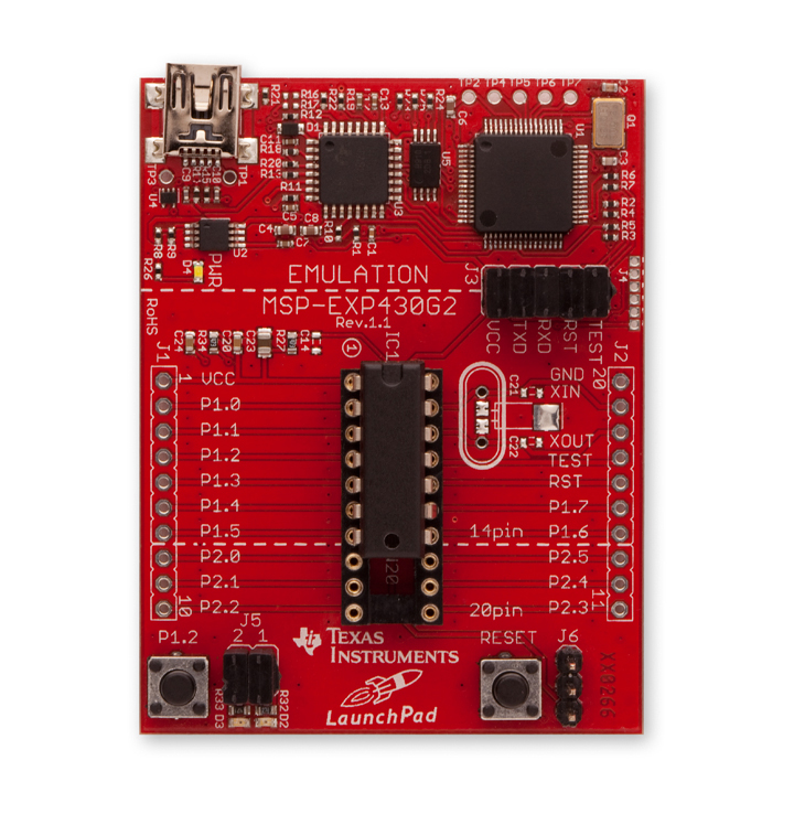
 If you've looked at the above links and decided the price is way too high, then let's look at the new LaunchPad! This board is a target board for 14 and 20 pin DIP components that also includes a programmer (see below) built into it. The best part of this option is that it comes at a price tag of a whopping $4.30! Though a new product, an online community has already started to develop around this development platform, and this option may be the easiest way to get started using the MSP430, especially for those with no experience in microcontrollers. The tutorial articles will use the LaunchPad to teach the basic uses and concepts of MSP430's.
Programmers
The MSP430 programmer is officially referred to as a Flash Emulation Tool (FET). These tools serve a dual purpose; they write programs to the MSP430, and they also can control the chip manually to allow for debugging of the program (see the discussion on debugging in the compiler section).
TI has two types of programming connections. You can use a 4-wire JTAG connection, which needs four pins of the MSP430 to write the program to the chip's memory, or you can use a 2-wire (Spy-bi-wire, or SBW) connection, which obviously needs only two pins to write the program. The 4-wire JTAG can be used to program any of the MSP430's, but the SBW only works with some of them. While you might think the SBW interface only works on some of the smaller, lower end chips, it's not the case; in fact it seems TI is including SBW capability in all of its new designs, including some of the new and powerful MSP430x5xx family. (A list of compatible parts can be found in slau157n. Look for Table 2-1.) The real trade-off for using SBW is the programming speed; SBW runs about ten times slower than JTAG. However, MSP430 programs tend to be quite small, often less than 2 kb in size. Unless you're really impatient, programming and debugging speed shouldn't be much of an issue, unless you're working in time critical environments.
The standard TI FET comes in a USB interface, though an older serial-port interface is also available. This FET can program by either JTAG or SBW through a 14 pin (2x7) header pin connector. Other companies have made their own equivalents to the TI programmer, often at a lower price.
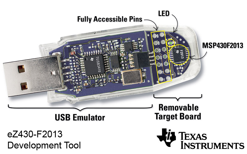
If you are satisfied with SBW programming, there are some cheaper options available. The TI eZ430 system has an FET interface in a USB stick form factor (picture here). Unfortunately, the pins are very close to the computer, so your board must also be close, or you'll need to make your own cable to connect your board to the stick. (Remember that SBW is a 2-wire interface; you might notice the connection to the USB portion has 4 pins. The MSP430 also needs power, and most FET's can provide power directly. Two more pins are needed for Vcc and ground. The minimum needed for JTAG would be 6 pins.)
The LaunchPad comes with its own SBW FET built in. The emulation portion of the board can also be used to program MSP430's externally. A set of 6 pins are available for this, giving power, the SBW interface, and two extra pins for communicating through the USB controller on the board.
Compilers
Two professional compilers for the MSP430 also make free versions available; IAR Systems and Code Composer Studio. The free versions limit the code size you can create (4 kb for IAR, 16 kb for CCS), but many of the MSP430 variations have less memory than this anyway. For larger programs, you can either purchase the full compilers, or use the mspgcc open source compiler. Information on using mspgcc will be given at some point on this blog, but for the purposes of the tutorial we'll use TI's Code Composer Studio. Those who prefer IAR's compiler should be able to do so without much difficulty from the tutorial here.
One of the most important tools for a development environment is a debugging interface. IAR and CCS both come with one built in to the IDE, but mspgcc users will need mspdbg to do debugging. The debugging feature allows you to step through the code and see how it changes the settings and configurations of the MSP430 step by step, helping you to verify that the system is working the way it should and to view the contents of the registers and variables in memory. Early on in the tutorial posts we'll look at using the debugger effectively.
Power
The LaunchPad is powered through the USB interface, and whenever an FET is used this option is available. If you want to implement your design in a stand-alone system, however, you'll need to provide power to the circuit in some way.
The MSP430 is an ultra-low power device, and performs very well using standard consumer batteries. The MSP430 will run with anywhere between 1.8 V and 3.6 V, though at least 2.2 V is needed to do any programming to the chip. Keep in mind that the speed at which the chip is able to run also depends on the voltage; though it's capable of running up to 16 MHz, at 1.8 V an MSP430F2001 cannot run any faster than 6 MHz. This image is an excerpt from the MSP430F2001 datasheet, showing how the supply voltage affects the operating frequency.

Check the datasheet for your particular MSP430 device for a similar plot to see what frequencies are available at the voltage you choose to power your design.
Target Boards
The MSP430 can be programmed while inside its final circuit, if the proper electrical connections are available, or outside of its intended place by using a target board. These boards are built in a way that the chip can be inserted temporarily, programmed, and then removed and mounted into the circuit in which it's intended to be used. A well built target board will also make it possible to prototype, or connect to other circuits so that the chip can be used while still in its target board. TI makes nice target boards for some of the form factors used for their MSP430's, such as the MSP-TS430PW28. While a little costly, most of the expense comes in the fancy, spring-loaded, zero insertion force (ZIF) socket for holding the chips. For a little more, you can even get bundles that include a full programmer. Target boards are not too difficult to design, either; we'll look at how to do just that in a later tutorial.
A fancier type of board is the experimenter's board (also may be called a development board). This board can be similar to a target board and use a socket to make the chip placement temporary, or it can have the MSP430 soldered in place. Experimenter's boards come with other parts like LED's, buttons, and perhaps speakers, serial or ethernet ports, and a wide variety of devices or connections that interface with the outside world. TI makes a few of these, such as the MSP-EXP430F5438. Other vendors like Olimex also make this type of board, usually at a lower price tag, but sometimes with older families of the MSP430.
Programmers
The MSP430 programmer is officially referred to as a Flash Emulation Tool (FET). These tools serve a dual purpose; they write programs to the MSP430, and they also can control the chip manually to allow for debugging of the program (see the discussion on debugging in the compiler section).
TI has two types of programming connections. You can use a 4-wire JTAG connection, which needs four pins of the MSP430 to write the program to the chip's memory, or you can use a 2-wire (Spy-bi-wire, or SBW) connection, which obviously needs only two pins to write the program. The 4-wire JTAG can be used to program any of the MSP430's, but the SBW only works with some of them. While you might think the SBW interface only works on some of the smaller, lower end chips, it's not the case; in fact it seems TI is including SBW capability in all of its new designs, including some of the new and powerful MSP430x5xx family. (A list of compatible parts can be found in slau157n. Look for Table 2-1.) The real trade-off for using SBW is the programming speed; SBW runs about ten times slower than JTAG. However, MSP430 programs tend to be quite small, often less than 2 kb in size. Unless you're really impatient, programming and debugging speed shouldn't be much of an issue, unless you're working in time critical environments.
The standard TI FET comes in a USB interface, though an older serial-port interface is also available. This FET can program by either JTAG or SBW through a 14 pin (2x7) header pin connector. Other companies have made their own equivalents to the TI programmer, often at a lower price.
If you are satisfied with SBW programming, there are some cheaper options available. The TI eZ430 system has an FET interface in a USB stick form factor (picture here). Unfortunately, the pins are very close to the computer, so your board must also be close, or you'll need to make your own cable to connect your board to the stick. (Remember that SBW is a 2-wire interface; you might notice the connection to the USB portion has 4 pins. The MSP430 also needs power, and most FET's can provide power directly. Two more pins are needed for Vcc and ground. The minimum needed for JTAG would be 6 pins.)
The LaunchPad comes with its own SBW FET built in. The emulation portion of the board can also be used to program MSP430's externally. A set of 6 pins are available for this, giving power, the SBW interface, and two extra pins for communicating through the USB controller on the board.
Compilers
Two professional compilers for the MSP430 also make free versions available; IAR Systems and Code Composer Studio. The free versions limit the code size you can create (4 kb for IAR, 16 kb for CCS), but many of the MSP430 variations have less memory than this anyway. For larger programs, you can either purchase the full compilers, or use the mspgcc open source compiler. Information on using mspgcc will be given at some point on this blog, but for the purposes of the tutorial we'll use TI's Code Composer Studio. Those who prefer IAR's compiler should be able to do so without much difficulty from the tutorial here.
One of the most important tools for a development environment is a debugging interface. IAR and CCS both come with one built in to the IDE, but mspgcc users will need mspdbg to do debugging. The debugging feature allows you to step through the code and see how it changes the settings and configurations of the MSP430 step by step, helping you to verify that the system is working the way it should and to view the contents of the registers and variables in memory. Early on in the tutorial posts we'll look at using the debugger effectively.
Power
The LaunchPad is powered through the USB interface, and whenever an FET is used this option is available. If you want to implement your design in a stand-alone system, however, you'll need to provide power to the circuit in some way.
The MSP430 is an ultra-low power device, and performs very well using standard consumer batteries. The MSP430 will run with anywhere between 1.8 V and 3.6 V, though at least 2.2 V is needed to do any programming to the chip. Keep in mind that the speed at which the chip is able to run also depends on the voltage; though it's capable of running up to 16 MHz, at 1.8 V an MSP430F2001 cannot run any faster than 6 MHz. This image is an excerpt from the MSP430F2001 datasheet, showing how the supply voltage affects the operating frequency.

Check the datasheet for your particular MSP430 device for a similar plot to see what frequencies are available at the voltage you choose to power your design.
Aside from consumer batteries, you can also power your design from the wall if you use a transformer and voltage regulator. Later on we'll look at the ideas to consider in using a voltage regulator. You may be interested in looking into using a solar cell to power your design, or other creative ways to get power.
Following the Tutorial
This tutorial will use the TI LaunchPad with its SBW emulator to explain how many of the features of the MSP430 work and how to use them effectively. Examples will be done using CCS v4 as the development environment. If you have these two pieces (for a total price of $4.30!), you'll have enough to get started. If you happen to have another emulation tool or target/experimenter's board, feel free to use what you already have; everything done in the tutorial is easy to modify to whatever MSP430 platform you're using. When we move on to interfacing outside of the LaunchPad system, we'll provide some good ideas on how to do that cheaply and cleanly. Once you have the basics down, you should be able to design any system in which you can put in and program an MSP430.
08 June 2010
Crystal Timers
The MSP430 has great internal clocks, but for time-critical applications we need something more stable. Crystals are one of the best oscillators available, and are quite stable if they are handled correctly. While it would make more sense to look at timers starting with the internal clocks, I have an immediate need to work toward USB communication, which requires the use of crystals for timing.
MSP430's can have up to two crystals to set clocks externally. XT1 is typically a low frequency (< 1 MHz), which is why it is usually referred to as LFXT1 (low frequency crystal 1). All of TI's MCU's have pins that can be used with one of these low frequency crystals. The chips can also be configured to use a high frequency crystal if needed. Many MCU's also have an XT2 built specifically for HF oscillators. The exact frequency chosen depends on the application, but a commonly used frequency is 32,768 Hz, often referred to as 32 kHz even though it is not a decimal kHz. It is, however, a binary kHz, which is why it is a convenient frequency for timing applications. In exactly 1 second, the crystal will go through 2**15 oscillations. When 15 bits roll over, the timer is reset to zero, and every reset happens at exactly 1 s intervals.
Connecting a crystal to an MSP430 is a little tricky. Fortunately, TI has provided some excellent documentation to help. Essentially, the crystal should be close to the chip and isolated from other signals in the circuit. Crystals have particular capacitances that need to be matched correctly in order to be accurate. The newer MSP430's (anything but the x1xx series, really) are able to set capacitors to a few values internally. The target board I received included a 32 kHz crystal with 12.5 pF capacitance. 12.5 pF is one of the values that can be set internally, so the crystal can be put on the board without needing external capacitors. It does require, however, setting the MCU software initially to have the right capacitance internally. This is done by setting the appropriate value to the XCAPx bits in BCSCTL3 (Basic Clock System Control 3). The header files include the values XCAP_x to help set the proper bits correctly. For my 12.5 pF crystal, XCAP_3 is the correct selection. Note in the code below rather than setting BCSCTL3 = XCAP_3, |= is used to only change the XCAPx bits in the register.
In the errata for the MSP430F2132, it mentions that the MCU sometimes has issues with crystals with an equivalent series resistance (ESR) less than 40 kΩ. The crystals I purchased have 30 kΩ ESR, but seem to work fine. I don't know if my fumbling soldering technique increased the resistance sufficiently or if it just appears to work and isn't perfectly accurate, but it seems close enough for now. Future workarounds are to pick a crystal with a higher ESR or to add a resistor into the circuit as explained in TI's application note about this particular erratum.
Once the crystal is in place, it should be checked to be certain it is oscillating. This post's program won't be able to prove accuracy of the crystal, but it at least shows that the crystal oscillates and can be used. The crystal's frequency is accessed with the auxiliary clock ACLK.
/* 32kcrystalF2132: quick program to test the functionality of a watch crystal
* soldered to the target board. Flashes an LED on P1.0 at 2 Hz.
*/
#include
#define LED BIT0
void main(void) {
int i; // internal counter
WDTCTL = WDTPW + WDTHOLD; // turn WDT off
P1OUT = 0x00;
P1DIR = LED;
BCSCTL3 |= XCAP_3; // xtal has 12.5 pF caps
TACCR0 = 16383; // f_xtal / 2 - 1 gives 2 Hz
TACTL = TASSEL_1 + MC_1 + TACLR; // ACLK + Up Mode + Clear timer
for (;;) {
while ((TACTL & BIT0) == 0) { // wait for timer to reach TACCR0
}
TACTL &= ~BIT0; // reset TAIFG
P1OUT |= LED; // LED on
for (i=0; i<0x314; i++) { // short delay
}
P1OUT &= ~LED; // LED off
}
} // main
The comments in the code should help explain how the program works, but it's worth taking some time to explain some of the features of Timer A.
- Any of the timers in an MSP430 can be configured to run off of any of the clocks (MCLK, SMCLK, ACLK) by setting the TASSELx bits in TACTL. TASSEL_1 in the header file configures the timer to run off the auxiliary clock connected to the crystal.
- The MCx bits set the mode of the timer. These are initialized to 0 when the MCU is powered, keeping the timers turned off and conserving power. MC_1 in the header file configures the timer in "Up Mode", which counts upward until it reaches a value set in TACCR0. MC_2 sets the timer in "Continuous" mode, which counts upward until the counter rolls over (from 0x0000 to 0xFFFF). This code could use continuous mode, but would then only be able to flash the LED at exactly 1 Hz. Using up mode allows you to set the flash to exact values at frequencies higher than 1 Hz and up to 32 kHz.
- The TACLR bit clears the timer so that it starts at 0 from wherever the bit is set. This is useful because the timer continues to run even when the code is not using it or looking at it. If an exact time is needed, the timer should be cleared to be certain it counts the right number of times before reaching TACCR0.
- The TAIFG bit (this is bit 0 in TACTL) is set when the timer rolls over, either at the top in continuous mode or at TACCR0 in up mode. The code watches this bit to know when to flash the LED. Note that the flag must be reset manually. The timer continues to run while the code is turning on the LED, waiting briefly (0x314 is just a random value I picked for a short flash), and turning off the LED, so when the loop starts again, the timer has already been running. This feature is very useful for exact timing applications, because we don't need to be concerned about accounting for the processing time between loops. As long as the program takes less time to run than intervals between TAIFG being set, the program will execute at exactly the time we require.
One final note about the value set to TACCR0--Since the timer starts at 0, and 0xFFFF coresponds to 65,535, the timer can only trigger at integer values between these two. For this crystal, 32,768 counts would correspond to 1 s, so by setting TACCR0 to 32767 we would trigger every second. The correct way to get the exact timing is to count to f/n - 1 (using whole fractions of the oscillation frequency, i.e. 1/2 s., 1/3 s., 1/4 s., etc as the period between flashes), so 1/3 s would be TACCR0 = (1/3) / 32,768 - 1 = 10,922. As long as this value is less than 65,536, nothing other than setting this register needs to be done.
07 June 2010
Configuring Inputs & Outputs
The MSP430 becomes especially useful in the laboratory environment when it is used to collect information and send information in conjunction with equipment and measuring instruments. To do this, the chip needs an electrical connection with the transducers, or motors, or whatever other devices are being used. These connections are made through input and output ports.
All MSP430 microcontrollers have general input/output ports. The larger chips, of course, have more ports available, but even the smallest chips have pins for input and output. One of the nice features of these microcontrollers is that the pins can be used as an input or as an output; each port is normally associated with up to 8 pins, and each can individually be an input or an output, and can even change function in the middle of a program. The MSP430F2132 has 3 ports (24 pins) available that can be configured for general I/O.
Keep in mind that,while for low power systems the MSP430 is able to drive devices directly (assuming they run well at 3.3V), many devices will need to be controlled/sampled with transistors and amplifiers, or other intermediate components, to prevent damaging the MSP430 with high voltages or currents.
Part of the memory space in the MSP430 is set aside as specific registers, which are used to store information on how the chip should behave. The behavior of each pin on a port is controlled with the register P#DIR, where the # corresponds to the particular port being used. P#DIR is a 1 byte value with each bit corresponding to one pin for the port. For example, the 3rd bit on P1DIR controls P1.3. (Remember that the bits are numbered 0-7, not 1-8, so the 3rd bit is actually the 4th least significant digit.) When a bit in P#DIR is set to 0, the pin is configured as an input. When it is set to 1, the pin works as an output. As an example, if P3DIR = 0b01100101, then P3.0, P3.2, P3.5, and P3.6 are set to be outputs, while P3.1, P3.3, P3.4, and P3.7 are set to be inputs.
Setting the value on an output is done through the P#OUT register. This register is again a 1 byte value, each bit corresponding to each pin on a port. In the previous post, the LED connected to P1.0 was turned on and off by writing a value to the 0th bit of P1OUT. P1OUT = 0x01 (which corresponds to 0b00000001) turns on the LED by applying Vcc to the pin. P1OUT = 0x00 turns off the LED by grounding the pin. If we had set P1OUT = 0x03 (0b00000011), the LED would have turned on since bit 0 is set to be high. What about P1.1, since the second bit is high? In this case, since P1DIR was configured to have P1.1 an input, no voltage is applied to the pin, but the number is rather stored in a buffer. If we reconfigure P1.1 to be an output after setting P1OUT as above, then it starts with Vcc applied to the pin when switched. It is a good idea to always set P#OUT to the desired initial values before setting P#DIR to be certain the buffer values match what we want the pin behavior to be when the device is turned on. (It wouldn't be so good to turn on the controller and immediately start moving a motor before setting the output to keep the motor from turning.)
Reading inputs is done with the P#IN register. The values in this register correspond to the current voltage level on each pin in the port. Thus, for pins configured as outputs, the bits in P#IN and P#OUT are the same. When an MSP430 of any kind restarts, it defaults to setting the port pins as inputs. (There are exceptions for some pins, such as those intended to connect to a crystal oscillator. See your chips datasheet for details.)


A quick comment on some parts of the program: the header files include definitions for each individual bit. BIT0 is defined as 0b00000001, BIT1 as 0b00000010, and so on. I've used two definitions to make the program even more clear. I use LED to refer to bit 0 and BTN to refer to bit 3, since those are the bits used in the circuit design for the led and the button. The program also makes a function call. The purpose of the short delay function is to deal with switch bounce. Most mechanical switches will flip on and off a few times when pressed or released. To make certain the led doesn't rapidly turn on and off with the bouncing, a delay is used. The program constantly checks the current state of the button. Each check delays for a brief moment so that any bouncing occurs while the program is in the delay loop.
The method used for switching the output values is also very useful. Any bit and 0 returns 0, while any bit and 1 returns the original bit. ~LED gives the value 0b11111110, in this case, so bits 1-7 remain unchanged while bit 0 is set to 0 when you set P1OUT to P1OUT & ~LED. Any bit or 0 returns the original bit, while any bit or 1 returns 1. Setting P1OUT to P1OUT | LED has the opposite effect of setting bit 0 to 1.
/* buttonF2132: I/O configuration test that lights an LED when a push button is
* pressed. The LED is connected to P1.0, active high. BTN is connected to
* P3.3, active high (ie. when pushed gives a positive voltage, normally gnd.)
*
* Also demonstrates bit manipulation and function calling. The delay function
* accommodates switch bouncing.
*/
#include
#define LED BIT0 // P1.0
#define BTN BIT3 // P3.3
void delay(void);
void main(void) {
WDTCTL = WDTPW + WDTHOLD;
P1OUT &= ~LED; // initialize output by ensuring bit 0 is 0.
P1DIR = LED; // set bit 0 to output
P3DIR = 0x00; // unnecessary, but explicitly states P3 is all inputs.
for (;;) {
if ((P3IN & BTN) == 8) {
P1OUT |= LED; // set bit 0 to 1, turn on LED
delay(); // delay to prevent switch bounce
}
else {
P1OUT &= ~LED; // set bit 0 to 0, turn off LED
delay();
}
} // infinite loop
} // main
void delay(void) {
int i;
for (i=0; i<0xFF; i++) {
}
} // delay
All MSP430 microcontrollers have general input/output ports. The larger chips, of course, have more ports available, but even the smallest chips have pins for input and output. One of the nice features of these microcontrollers is that the pins can be used as an input or as an output; each port is normally associated with up to 8 pins, and each can individually be an input or an output, and can even change function in the middle of a program. The MSP430F2132 has 3 ports (24 pins) available that can be configured for general I/O.
Keep in mind that,while for low power systems the MSP430 is able to drive devices directly (assuming they run well at 3.3V), many devices will need to be controlled/sampled with transistors and amplifiers, or other intermediate components, to prevent damaging the MSP430 with high voltages or currents.
Part of the memory space in the MSP430 is set aside as specific registers, which are used to store information on how the chip should behave. The behavior of each pin on a port is controlled with the register P#DIR, where the # corresponds to the particular port being used. P#DIR is a 1 byte value with each bit corresponding to one pin for the port. For example, the 3rd bit on P1DIR controls P1.3. (Remember that the bits are numbered 0-7, not 1-8, so the 3rd bit is actually the 4th least significant digit.) When a bit in P#DIR is set to 0, the pin is configured as an input. When it is set to 1, the pin works as an output. As an example, if P3DIR = 0b01100101, then P3.0, P3.2, P3.5, and P3.6 are set to be outputs, while P3.1, P3.3, P3.4, and P3.7 are set to be inputs.
Setting the value on an output is done through the P#OUT register. This register is again a 1 byte value, each bit corresponding to each pin on a port. In the previous post, the LED connected to P1.0 was turned on and off by writing a value to the 0th bit of P1OUT. P1OUT = 0x01 (which corresponds to 0b00000001) turns on the LED by applying Vcc to the pin. P1OUT = 0x00 turns off the LED by grounding the pin. If we had set P1OUT = 0x03 (0b00000011), the LED would have turned on since bit 0 is set to be high. What about P1.1, since the second bit is high? In this case, since P1DIR was configured to have P1.1 an input, no voltage is applied to the pin, but the number is rather stored in a buffer. If we reconfigure P1.1 to be an output after setting P1OUT as above, then it starts with Vcc applied to the pin when switched. It is a good idea to always set P#OUT to the desired initial values before setting P#DIR to be certain the buffer values match what we want the pin behavior to be when the device is turned on. (It wouldn't be so good to turn on the controller and immediately start moving a motor before setting the output to keep the motor from turning.)
Reading inputs is done with the P#IN register. The values in this register correspond to the current voltage level on each pin in the port. Thus, for pins configured as outputs, the bits in P#IN and P#OUT are the same. When an MSP430 of any kind restarts, it defaults to setting the port pins as inputs. (There are exceptions for some pins, such as those intended to connect to a crystal oscillator. See your chips datasheet for details.)
The following program makes use of I/O ideas to turn the LED on P1.0 on and off by using a push-button switch on P3.3. The push button used is connected with a resistor to ground so that when unpressed the output doesn't float, but is tied to ground. When pressed, the output is connected to Vcc. This connection also causes a small current to flow through this "pull-down" resistor. A push button can also reverse this behavior by having the output tied with a "pull-up" resistor to Vcc and grounding the output when pressed. The output of the button can be connected to an input on the MSP430 in either case. For the pull-down setup, the input reads 0 when unpressed and 1 when pressed. I've done this with an external circuit, connecting my push buttons to Vcc and ground with external resistors enclosed in a small box. In the video below, the red button is tied to a pull-up resistor, and the black button to a pull-down resistor. (The black is used in the program below.) The MSP430 actually is built with resistors inside the chip, and each input pin can be set with pull-up or pull-down resistors individually without external pieces. We'll examine how to do that in another post soon.
A quick comment on some parts of the program: the header files include definitions for each individual bit. BIT0 is defined as 0b00000001, BIT1 as 0b00000010, and so on. I've used two definitions to make the program even more clear. I use LED to refer to bit 0 and BTN to refer to bit 3, since those are the bits used in the circuit design for the led and the button. The program also makes a function call. The purpose of the short delay function is to deal with switch bounce. Most mechanical switches will flip on and off a few times when pressed or released. To make certain the led doesn't rapidly turn on and off with the bouncing, a delay is used. The program constantly checks the current state of the button. Each check delays for a brief moment so that any bouncing occurs while the program is in the delay loop.
The method used for switching the output values is also very useful. Any bit and 0 returns 0, while any bit and 1 returns the original bit. ~LED gives the value 0b11111110, in this case, so bits 1-7 remain unchanged while bit 0 is set to 0 when you set P1OUT to P1OUT & ~LED. Any bit or 0 returns the original bit, while any bit or 1 returns 1. Setting P1OUT to P1OUT | LED has the opposite effect of setting bit 0 to 1.
/* buttonF2132: I/O configuration test that lights an LED when a push button is
* pressed. The LED is connected to P1.0, active high. BTN is connected to
* P3.3, active high (ie. when pushed gives a positive voltage, normally gnd.)
*
* Also demonstrates bit manipulation and function calling. The delay function
* accommodates switch bouncing.
*/
#include
#define LED BIT0 // P1.0
#define BTN BIT3 // P3.3
void delay(void);
void main(void) {
WDTCTL = WDTPW + WDTHOLD;
P1OUT &= ~LED; // initialize output by ensuring bit 0 is 0.
P1DIR = LED; // set bit 0 to output
P3DIR = 0x00; // unnecessary, but explicitly states P3 is all inputs.
for (;;) {
if ((P3IN & BTN) == 8) {
P1OUT |= LED; // set bit 0 to 1, turn on LED
delay(); // delay to prevent switch bounce
}
else {
P1OUT &= ~LED; // set bit 0 to 0, turn off LED
delay();
}
} // infinite loop
} // main
void delay(void) {
int i;
for (i=0; i<0xFF; i++) {
}
} // delay
Reader Exercise: Write a program that controls two LEDs as in the previous exercise. Use two other pins in port 1 as inputs for two buttons, one with a pull-up resistor and one with a pull-down resistor. Have each button control one of the two LEDs. Set one LED to be off unless its button is pressed, and set the other LED to be on unless its button is pressed.
17 May 2010
Writing a first program
The typical "Hello, World!" of microcontrollers is a blinking LED. The F2132 target board has an LED connected to one of the pins on port 1 (P1.0, pin 21) by a jumper. Here's what a typical C program for this looks like:
/* blinkyF2132: test program toggling an LED connected to P1.0 on the
* MSP430F2132.
*/
#include <msp430x21x2.h>
void main(void) {
int i;
WDTCTL = WDTPW + WDTHOLD;
P1DIR = 0x01;
P1OUT = 0x00;
for (;;) {
P1OUT ^= 0x01;
for (i=0; i<0xFFFF; i++) {
} // delay
} // infinite loop
} // main
This program is very simple, and not really useful for much other than to reassure you that everything works right and that you can actually program the msp430. Below is a short video of my target board running the program. There are certainly more elegant ways to do this trivial task, but this method is a good way to start and doesn't require much understanding of the MCU itself.
/* blinkyF2132: test program toggling an LED connected to P1.0 on the
* MSP430F2132.
*/
#include <msp430x21x2.h>
void main(void) {
int i;
WDTCTL = WDTPW + WDTHOLD;
P1DIR = 0x01;
P1OUT = 0x00;
for (;;) {
P1OUT ^= 0x01;
for (i=0; i<0xFFFF; i++) {
} // delay
} // infinite loop
} // main
- The first thing to note is the included header file; all msp430 compilers come with a collection of these files that define specific tools and behavior for the various families of the controllers. In this case, since I am using an F2132, I use the x21x2 family header. (Edit: looking at the header file included in CCS4, this format for the header file is considered legacy. The preferred usage would be specific to the chip itself, so in this case you would include the msp430f2132.h header file.)
- WDTCTL, P1DIR, P1OUT and the like are all convenient keywords defined in the header file.
- WDTCTL points to the word (2 bytes) controlling the watchdog timer. This timer resets the chip after a certain amount of time has passed. To keep our program running, it needs to be disabled. The 8 least significant bits (0 through 7) of WDTCTL control the behavior of the watchdog timer. Bit 7 specifically puts the timer on hold if set to 1. In the header file, WDTHOLD is defined to be a 2 byte value with only the 7th bit set to 1 (ie. 0b0000000010000000, or in hex, 0x0080). By writing WDTHOLD to WDTCTL, we turn off the timer.
- WDTCTL only uses 1 byte for its control; the 8 most significant bits are set up as a key to prevent a program from inadvertently changing the configuration. Hence, to write to WDTCTL you need to include a password of sorts. This password is the value 0x5a, and the header defines WDTPW to be 0x5a00. By adding this value to WDTHOLD you end up writing the value 0x5a80 to WDTCTL--which satisfies the necessary key and sets the hold bit to 1. (Note that you could also use WDTPW | WDTHOLD instead of adding them. They have the same effect in this case, but the TI examples use +, so I chose to use that convention.)
- Each port can configure each of its 8 pins to be inputs or outputs individually. On the target board, the LED is on P1.0, so P1DIR is set to have bit 0 to be the value 1 (output) and each of the other bits 0 (input). Writing 0x01 (0b00000001) to P1DIR configures it this way.
- P1OUT controls the digital values on the output pins of P1. In this program, 0x00 sets the outputs all to zero, and 0x01 sets all but pin 0 to zero with pin 0 at 1. The LED is connected with its cathode at ground, so a high value on P1.0 turns on the LED. Thus 0x00 is off, 0x01 is on.
- After setting up the configuration of the MCU, the program then enters the infinite loop: for (;;) { }. This step may seem odd at first, but since we want our controller to keep working, we can't have a program that terminates. Practically, without the loop the MCU would then continue trying to execute statements in the next memory spaces, eventually reading well beyond the actual program to unpredictable results.
- Inside the infinite loop, the program changes the value on P1.0. The ^, which is the C symbol for the exclusive or operation, turns the LED on if it is off, and off if it is on. Another for loop causes a delay between toggles on the LED. The length of the delay depends on how far the iterator i has to count. (It also depends on the frequency at which the MCU is operating; a faster clock speed makes the iteration count faster.)
This program is very simple, and not really useful for much other than to reassure you that everything works right and that you can actually program the msp430. Below is a short video of my target board running the program. There are certainly more elegant ways to do this trivial task, but this method is a good way to start and doesn't require much understanding of the MCU itself.
Reader Exercise: Write a similar MSP430 program using the MSP430F2001 to alternate blinking LEDs on ports P1.2 and P1.7 (ie. LED 1 is on, LED 2 is off. After some time, they switch to LED 1 off, LED 2 on. The F2001 is a 14 pin MSP430 that comes in PDIP, TSSOP, and QFN packages. P1.2 is pin 4, P1.7 is pin 9.)
Software
A few options exist for programming the MSP430. A number of professional compilers are available, but for easy home and hobby use there are also free versions.
While I would prefer working in a linux environment, it seems mspgcc is difficult to use because of the state of msp430-gdbproxy, the software that communicates through the FET. It does not yet support some of the newer families of MCUs, and takes a good deal of effort to get working properly. It also does not seem to support 64 bit systems yet.
For now, CCS4 works quite well and so will be the IDE I use. Very little of what will be documented here depends specifically on the environment, however, and so the choice is pretty arbitrary. The 16 kb limit might sound small, but typical MCU programming is actually quite dense, and so a lot of projects can easily fit into that limit.
- IAR Embedded Workbench Kickstart (Referred to as EW430 in MSP430 Microcontroller Basics by John H. Davies)
- The free version is limited to 4 kb code size
- Works in Windows (32 and 64 bit versions)
- Code Composer Studio v.4 (CCS4)
- Free version is limited to 16 kb code size
- Works in Windows (32 and 64 bit versions)
- MSPGCC
- Unlimited code size, as it's open source software
- Works in Linux or Windows under Cygwin (32 bit)
While I would prefer working in a linux environment, it seems mspgcc is difficult to use because of the state of msp430-gdbproxy, the software that communicates through the FET. It does not yet support some of the newer families of MCUs, and takes a good deal of effort to get working properly. It also does not seem to support 64 bit systems yet.
For now, CCS4 works quite well and so will be the IDE I use. Very little of what will be documented here depends specifically on the environment, however, and so the choice is pretty arbitrary. The 16 kb limit might sound small, but typical MCU programming is actually quite dense, and so a lot of projects can easily fit into that limit.
05 May 2010
Hardware
TI makes a large variety of types and packages for the MSP430, from a basic, 14-pin PDIP to a 113-pin BGA Microstar. Selecting the right MCU depends on a number of factors, including the number and types of peripherals and devices that need to be controlled.
For the initial experiments, we'll use the MSP430F2132 and the 20/28 pin target board produced by TI. These can all be purchased in a single package, and can include the MSP-FET430UIF flash emulation tool for programming the MCU. This target board works with the x21x1 20-pin TSSOP variations and the x21x2 28-pin TSSOP variations. The package comes with 2 F2132's, which are the largest of the chips usable in this board. The x21x2 is useful for basic projects as it includes most of what could be needed, including an analog to digital converter. Nearly everything done at this site will be doable on nearly any of the MSP430's, however. Sometimes a small chip (even the new and inexpensive G-series types) will be sufficient, and some of the larger chips (with more pins) may be helpful in future projects.
 The F2132 features:
 In addition to the F2132, some experiments will make use of the MSP430F5438 and the Experimenter Board made by TI. The F5438 is the chip being used in my research, and so this combination gives me a way to program that particular chip while also providing an environment with lots of external devices and controls to use in experiments, including an LCD, accelerometer, and various interface devices.
Both boards can be powered by the FET or externally. A future post will look into various options for powering an MSP430 project, and many experiments will simply use a pair of alkaline AA batteries (3.0 V). Note that two AA's do not provide sufficient voltage for the processor to run at the full 16 MHz.
The equipment described here will not necessarily be appropriate for everyone, but are a convenient and useful place for me to start. As I stated earlier, the ideas approached here will be useful for other projects using different chips and boards as well. Next time we'll take a look at the software needed and start loading a simple program onto the chip.
For the initial experiments, we'll use the MSP430F2132 and the 20/28 pin target board produced by TI. These can all be purchased in a single package, and can include the MSP-FET430UIF flash emulation tool for programming the MCU. This target board works with the x21x1 20-pin TSSOP variations and the x21x2 28-pin TSSOP variations. The package comes with 2 F2132's, which are the largest of the chips usable in this board. The x21x2 is useful for basic projects as it includes most of what could be needed, including an analog to digital converter. Nearly everything done at this site will be doable on nearly any of the MSP430's, however. Sometimes a small chip (even the new and inexpensive G-series types) will be sufficient, and some of the larger chips (with more pins) may be helpful in future projects.

- 16 MHz clock (at full voltage)
- 8 kb flash memory
- 512 b RAM
- 24 General Purpose Input/Outputs
- 10-bit SAR A/D Converter
- Universal Serial Communication Interface (communicates via UART, LIN, IrDA, I2C, or SPI)
The target board is a useful format for testing without needing to create a custom PCB or solder the MCU to anything. It includes a socket designed to hold the TSSOP package. Included are header pins (male and female) to attach on either side of the socket as seen in the photo above. I've chosen to use the female pins, which allows me to connect wires to devices easily. It also provides some protection from an accidental short from a stray wire bridging two pins that the male pins would not provide. The general rule of thumb in rockets is that anything that is powered when disconnected (intentionally or accidentally) should be female, and that's the convention used here.
Also on the board is a place to connect a 32.678 kHz crystal for timing. The MCU has excellent timers internally, so the crystal is not always essential; it's good to have for time critical applications, though. The kit includes a 12.5 pF surface mount crystal, though one flaw in the board design is that there is no convenient way to ground the crystal case. One option might be to solder a wire to the case and fit into the via that connects to ground. The crystal included in my kit actually broke off of its fine leads when I was playing around with figuring out how to attach it, so I have not put a crystal on my target board yet. Plated through hole form factors may be usable since the mounting place for the crystal on the target board is PTH. A quick note about the capacitance of crystals--it seems the MSP430, or at least newer versions of it, are able to set the load capacitance internally via software, so other capacitances may be used; I'll use 12.5 pF since that's what came with the kit initially.

Both boards can be powered by the FET or externally. A future post will look into various options for powering an MSP430 project, and many experiments will simply use a pair of alkaline AA batteries (3.0 V). Note that two AA's do not provide sufficient voltage for the processor to run at the full 16 MHz.
The equipment described here will not necessarily be appropriate for everyone, but are a convenient and useful place for me to start. As I stated earlier, the ideas approached here will be useful for other projects using different chips and boards as well. Next time we'll take a look at the software needed and start loading a simple program onto the chip.
Subscribe to:
Posts (Atom)